Documentation Index
Fetch the complete documentation index at: https://retrocultmods.mintlify.app/llms.txt
Use this file to discover all available pages before exploring further.
Introduction
This is an instructional guide for the RetroCultMods Revival Kit for the Xbox 360 Gibson Xplorer. This build can be completed in under an hour and a half, but can take longer if you are thorough with the cleaning process. If you run into any issues during the build or have questions, click here!Parts Included
- Revival Kit Zeroboard (Strumboard/PCB)
- Revival Kit Fretboard
- 3D Printed Translucent Strumbar for Xplorer
- 5x 3D Printed Translucent Frets (rectangular)
- 5x 3D Printed Xplorer Fret Shims (only needed on model 95065)
- 3D Printed Kit Hardware
- Xplorer Breakout Board
- Detachable USB-C Board and bracket
- New Whammy Assembly
- Switch Puller
- Color Coded Wires and Auth Cable
- 10 foot nylon braided USB-A to USB-C cable
- Tube of lubricant
Images of all parts
Images of all parts
Revival Kit Zeroboard
Required Tools (not included)
Step-by-Step Installation Guide
1. Opening the Guitar
Flip the controller over so the Red Octane sticker on the back of the body is visible. The type of screws used on the outside shells will depend on the model of your guitar:
95055/95605 – PH1/PH2 Screws
95157.805 – T10 Screws
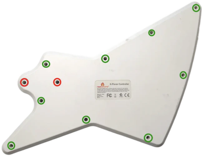
Body Screws
The screw marked in red is sometimes longer than the others; remember this for when you put everything back together!
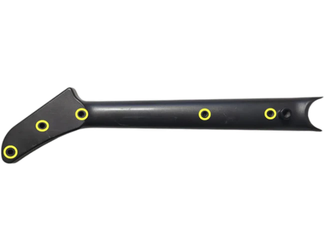
Neck Screws
Once the shell begins to open, slowly move down the rest of the shell until it pops open completely.
Repeat this process for the neck, using the opening at the neck connector and working towards the headstock. If the shell seems to gets stuck, DO NOT FORCE IT. Check to make sure you have removed all of the screws before continuing to pry the shell.
2. Removal of Original Parts
Now its time to remove the stock boards that will be replaced with the new boards included in the kit.
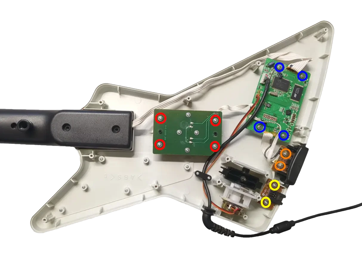
Internal Body Screws
Remove the 4x screws on the stock Strumboard.
Remove the 2x screws on the RJ11 port. (This board will not be replaced, so if you’d like to leave it in so there is no open hole in the shell after completing the kit, leave this board installed and cut the wires coming from it instead)
Remove the 4x screws on the stock input board.
Remove the 2x screws on the headset port.
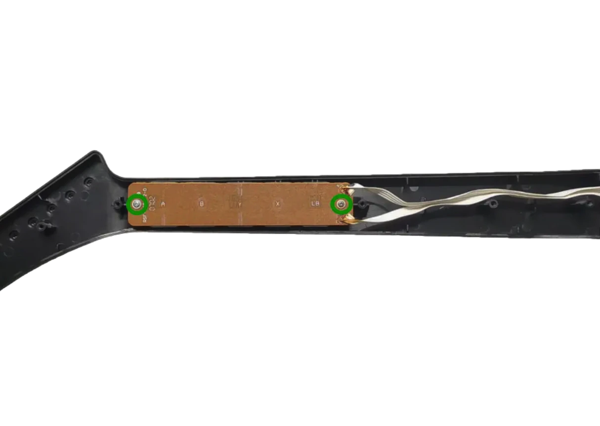
Internal Neck Screws
Remove the 2x screws from the stock Fretboard.
3. (Optional) Clean Your Guitar
In this step, I took a little bit of time to clean some parts of the guitar. I suggest being more thorough in your build, as your guitar may have finger grime from way back in the day!
A bit of rubbing alcohol and/or soap and water can go a long way. Make sure the parts are fully dry if you clean with soap and water.
Pro tip: Toothbrush, Dawn soap, and water.
4. Test Your Revival Kit
Before installing the Revival Zeroboard/Strumboard and Revival Fretboard, they should be tested for proper functionality.
Plug the Revival Fretboard into the Revival Zeroboard/Strumboard using the three included white cables. Make sure that each connection goes to the proper port. It is suggested to go one by one while installing.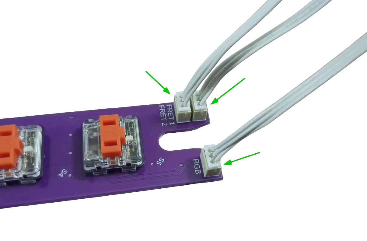
Plug your Revival Zeroboard/Strumboard into your computer, using the USB-C to USB-A cable included in the Revival Kit. You will plug it into the vertical USB-C port on the Zeroboard.
Open the RCM Programming Tool (click here to go to the download page). If the following screen appears for you, make sure to switch the DEVICE TYPE to **“Revival Kit”.**_ Click Erase and Configure. Do not touch the device while it is being programmed._


5. Prepping the New Strumbar (RGB Only)
IF YOU DID NOT ORDER THE 3D PRINTED CLEAR STRUM BAR, SKIP THIS STEP.
Before installing the new Strumboard, we need to transfer some pieces of the stock strumbar over to the new one:

Remove both of the circular spacers on each end of the strumbar. You can easily remove these by pushing them out with your finger from the inside of the strumbar.
Remove the four rubber pads on each foot of the strumbar. These can be lifted straight out of their slots.
Make sure you have all the stock parts you need:
- 1x Metal strumrod
- 2x Circular spacers
- 4x Rubber pads
Find the white tube of lubricant and apply a very small amount on each end of the metal strumrod, where it makes contacts with the circular spacers. Use for finger or a qtip to spread the lubricant out; we want only a thin layer of lubricant on the ends of the strumrod!
Put all of these parts into the new strumbar, in the same places as the stock strumbar. Insert the rubber pads into the slots in each of the feet of the new strumbar, insert the spacers into the circular cutouts on each end of the new strumbar, then insert the metal strumrod through the spacers.
If the strumbar slides up and down the metal rod too much for your liking, then you can install the wide, thin spacers included on the end of the component piece to fill in the gap. Place these under the stock strumbar spacers. You may need to stack multiple on each end to get your desired tolerance!
6. Installing the Revival Zeroboard (strumboard)
k
Slide the metal rod into the new strumbar. Then place the new strumbar into the slot that the stock strumbar sat in. Put the black brackets back into place.
Separate the small strum keycaps from the component piece and slot them into the stems of the strum switches. This is needed for a tighter strumbar feel.
Place the new strumboard on top of the black brackets, then screw in the new strumboard. If the stock screws are stripped, you can use the replacement Long Screws provided in the kit. Make sure each screw is snug, but do not over-tighten them, or you may scratch away the soldermask of the new strumboard!
7. Installing the Revival Fretboard
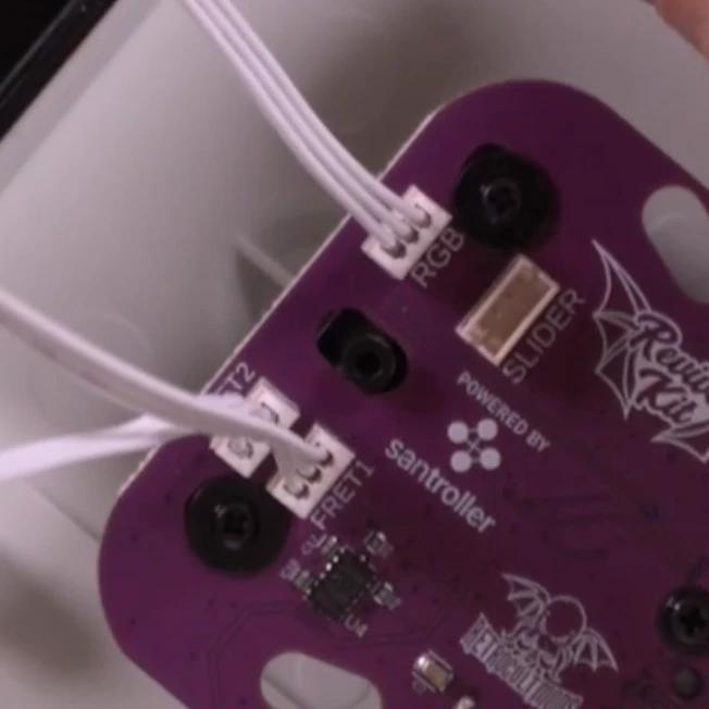
Connect one end of each of the White Wires into the RGB, FRET1, and FRET2 connectors on the Fretboard. Connect the other end of each White Wire to the corresponding RGB, FRET1, and FRET2 connectors on the Strumboard. I recommend doing one wire at a time to prevent mixing them up.
Remove the stock silicone pad and frets if they are still in the fret slots. Wipe the inside of the fret slots clean if they are dirty. Then apply a small amount of lubricant to your finger or a qtip and lightly coat the inside of the fret slots with lubricant. Make sure to wipe away any excess lubricant that my have spilled to the front of the neck shell!
Insert the translucent 3D printed frets_ provided in the kit. These frets must be used even if you do not want to use LEDs; the stock frets will not fit with the new Fretboard.
Model 95065 Xplorers will need to use the included fret shims to fit properly. Other models will not need shims._
Model 95065 Xplorers will need to use the included fret shims to fit properly. Other models will not need shims._
Place the new Fretboard onto the screw standoffs that the stock fretboard used to sit on (the red switches and white connectors should be facing down towards the Translucent Frets. Use 2 Long Screws to secure the new Fretboard.

8. Installing the Xplorer Breakout Board
Gather the Xplorer Breakout board (labelled 1X) and 4 Long Screws. Stock screws can also be used if they are not stripped
Make sure the rubber dome pads are still in place, then install the Xplorer Breakout board where the stock input board used to sit. Use the stock screws or included Long Screws to secure it.


9. Assembling and Installing the Whammy
10. Installing the Authentication Cable and USB-C Port

Slot the bottom bracket into the opening that the headset port used to sit in (use the picture for reference on the orientation of the bracket).
Slot the Authentication Cable vertically into the wide slot of the bracket. The strain relief should slot between the two existing screw standoffs on the body shell to hold it in place.
Using the yellow cable and the USB-C port board, plug the yellow wire into the connector on the USB-C port board.
Slot the USB-C port into the bracket in the orientation as shown in the picture. Wrap the yellow wire around the nearest standoff and route it towards the Zeroboard.


11. Test Inputs
Open the RCM Programming Tool on your computer (click here to go to the download page)_ If the following screen appears for you, make sure to switch the DEVICE TYPE to **“Revival Kit”.** Click Erase and Configure. Do not touch the device while it is being programmed._
12. Closing the Guitar
You’re almost done! Once you have ensured that each input works, we can close up the guitar!
Make sure none of the wires are in the way of any plastic standoffs, as this will damage them when closing the shell. I would recommend taping down the wires to ensure they are out of the way and not draped across any of the boards.
With the front body and neck shell facing down, put the rear neck shell onto the front neck shell. You may need to apply pressure to close the shell. If you feel like part of the shell will not snap into place, open it up and double check that there is nothing blocking the standoffs. Repeat for the body shell.
DON’T FORGET THE STRAP PEGS!
After both sides of the body are connected, install all of the screws you removed earlier:
Body Screws
The screw marked in red is sometimes longer_ than the others; remember this for when you put everything back together!_
Neck Screws
13. Calibrate Tilt and Whammy
Plug the guitar back into your computer and open RCM Programming Tool. Click Configure.
14. Configure Fret and Strum Bar Colors
Scroll to the fret and strum inputs and click the arrow to reveal the color selectors for your chosen input.

