Use this file to discover all available pages before exploring further.
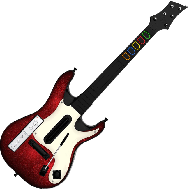
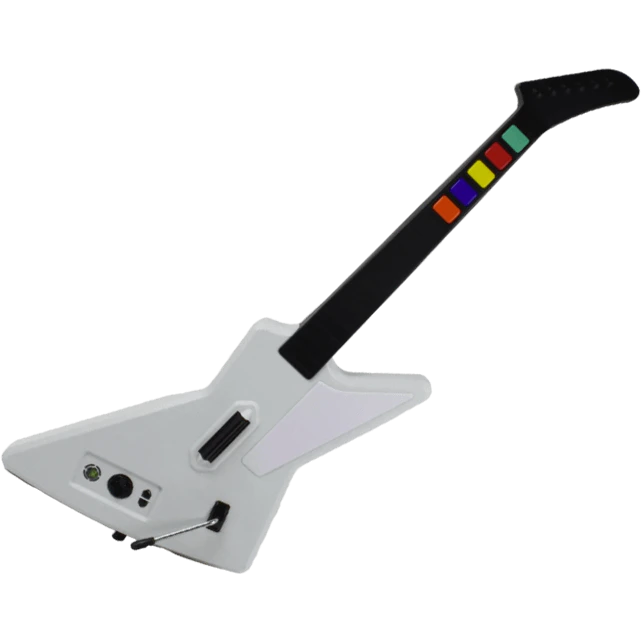
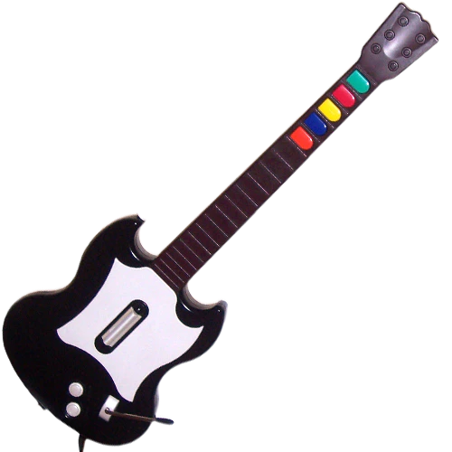
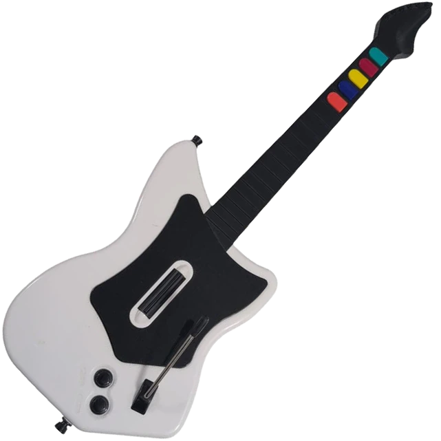
The RetroCultMods DIY Solder Kit contains everything you need to convert your official Red Octane Guitar Hero controller into a modded XInput guitar controller has nearly universal platform compatibility.
This kit REQUIRES both soldering equipment and knowledge to install!
We prefer Kester 44 solder. Usually they sell it in 1LB rolls, but you can get by with one of the 1oz tubes if you don’t plan on soldering often in the future.
Soldering Iron temperature:
600°F or 315°C (Leaded Solder)
675**°F or 360°**C (Lead Free Solder).I personally use the hotter temperature with leaded solder.Cold Joints can appear as a bubble or a more matte finish on your solder joint. If this happens, hold the iron and melt the solder again, but hold your iron there briefly so the heat transfers to the pins properly. If you’ve applied too much solder, use your solder wick.
How to use Solder Wick
To use solder wick, place the end of the wick over the solder you want to remove and then place your heated solder tip over it. The braid heats up and will suck up the solder. You can tell when the wick begins to pull the solder, as the wick will change color.
Flip the controller over so the Red Octane sticker on the back of the body is visible. The type of screws used on the outside shells will depend on the model of your guitar: 95055/95605 – PH2 Screws 95157.805 – T10 Screws
2
Begin removing the 11x body screws.The screws marked in red may be longer than the others; remember this for when you put everything back together! Note that some Xplorers will not have any longer screws.
3
Ensure that all of the screws are removed, and open the shell.Once the shell begins to open, slowly move down the rest of the shell until it pops open completely.If the shell seems to gets stuck, DO NOT FORCE IT. Check to make sure you have removed all of the screws before continuing to pry the shell.
4
Repeat this process for the neck, using the opening at the neck connector and working towards the headstock. There are 5x screws on the neck.Like the body, if the shell of the neck seems to gets stuck, DO NOT FORCE IT. Check to make sure you have removed all of the screws before continuing to pry the shell.
5
Cutting the Wires
1
Unscrew the control board.
2
Cut the whammy cables at the connection point on the control board.
3
Cut strumboard cable at the connection point on the control board.
4
Cut headphone cables on the end of the headphone board, as close as you can to the board.
5
Cut fretboard cable at the connection point on the control board.
6
If you want to continue using the original Xplorer cable, cut the five colored wires as close as you can to the control board. You will need an Xplorer Breakout Board.
Removing Existing Xplorer Components
Now its time to remove the stock boards that will be replaced with the new boards included in the kit.
1
Remove the 4x screws on the stock Strumboard.
2
Remove the 2x screws on the RJ11 (footpedal) port. (You can route your cable out of here if you are not using a USB-C Daughterboard Port)
3
Remove the 4x screws on the stock input board. (Keep all silicone pads and button pieces)
4
We will not be removing the headphone board.
5
Remove the 2x screws from the stock Fretboard. (We will not need the silicone pad)
Insert the Kailh Choc Low Profile Red Switches into the fretboard, making sure that you put it in the correct way like shown below.
2
Bend the thinner leg closest to the square solder pad down so it has contact or is very close to the solder pad.
3
Put a little bit of flux on each pad, then solder the leg to the pad. Repeat this for all 5 switches.
4
Tin your soldering tip and clean it with the brass wool.
5
Once you’ve soldered all 5 legs, insert the 90-degree Pin Headers into the circular solder pads like shown below and orient them in a way where the headers touch the other leg of the switch like shown below.
6
Add a dab of flux to the spot where the two pieces of metal touch to hold the 90-degree Pin Header in place.
7
This part is tricky.You must solder the 90 degree header to the leg of the switch. Apply heat to the area you added flux to, then apply solder. You want to make sure they are bound together with solder like shown below.
8
Once you’ve verified that all five headers have been soldered to their respective switch legs, flip the entire fretboard over. You must now connect the 90-degree Pin Headers to the fretboard. The circular pads around the headers are what must be soldered to, shown below.
9
Apply a small amount of flux, then carefully solder the pin header to the fretboard, being mindful to not touch the switch with soldering iron.
10
Using flush cutters, cut the excess metal of the header, leaving just the “mountain” shape of soldered metal, like shown below.
Place your Zeroboard down on the table, component side facing down
2
Insert the two strum switches included in the kit into the designated holes in the middle of the board. They will both only go in one way, with the two metal pins going into metal sockets.
3
Tape the switches down to the board, making sure that the switches are flush to the board or as flush as they can be.
4
Flip the Zeroboard over.
5
Begin the soldering process.
6
Tin your solder tip, then clean it with the brass wool.
7
Apply a little bit of solder, then carefully solder the two metal legs of both switches to their sockets.
Strip both ends of one set of wires by approximately 1cm. More is okay, you’ll just have to trim it after
2
Separate the wires by about an inch and a half.
3
Observe both the Zeroboard and Fretboard pins, you will see the following pins:
4
Make a mental gameplan of how you’ll approach the soldering. You can either solder all on one side at a time, or back and forth per wire.
5
Twist the ends of the wires so that there’s no loose strands of copper, then insert them one by one into each fret color socket and ground sockets like shown below.
6
Tin your solder tip and clean it with brass wool.
7
Apply flux to each pad, then begin soldering each wire/pad, making sure that the solder joints are not bridging.
MAKE SURE YOU ARE MATCHING BOTH ENDS OF THE WIRE TO THEIR RESPECTIVE SOCKETS. GREEN TO GREEN, RED TO RED, ETC.
Examples of clean solder joints and bridging are shown below.
8
Flip both boards over then use your flush cutters to snip off any loose wires.
9
Once you’ve verified that all five frets and ground have been soldered, plug the Zeroboard into your computer and test each input. Take this time to test the strum inputs as well.
10
THE NEXT STEPS ONLY APPLY IF YOU ARE INSTALLING THE RGB FRET KIT THE NEXT STEPS ONLY APPLY IF YOU ARE INSTALLING THE RGB FRET KIT THE NEXT STEPS ONLY APPLY IF YOU ARE INSTALLING THE RGB FRET KIT THE NEXT STEPS ONLY APPLY IF YOU ARE INSTALLING THE RGB FRET KIT THE NEXT STEPS ONLY APPLY IF YOU ARE INSTALLING THE RGB FRET KIT
11
Now that you’ve soldered the fret inputs, it’s time to solder the RGB. Carefully observe both the fretboard and Zeroboard. You will see MOSI, SCK, and VBUS. VBUS is scrunched up close to a GND input, but we’ve labeled it in this picture below.
12
Split the remaining 6-pin 12 inch wire in half so it becomes two 3-pin wires. Then strip the ends like before. Twist the copper wires so there’s no loose strands.
13
Carefully insert them into the MOSI, SCK, and VBUS sockets, being careful that no loose strands touch another socket.
14
Tin your solder tip and clean it with brass wool.
15
Begin soldering each wire/pad, making sure that the solder joints are not bridging.
16
Flip both boards over then use your flush cutters to snip off any loose wires.
17
Plug the Zeroboard into your computer and test the RGB LEDs.
Snip the wires connected to the whammy potentiometer, on the far end so that you have a lot of wire to work with, shown below.
2
Strip the end of the three wires. If they aren’t already separated, separate them to make it easier to solder.
3
Find the VCC, ADC, and GND solder pads on the corner of the Zeroboard
4
The middle wire connected to the whammy potentiometer MUST go into the “ADC” socket. The other wires can go on either side, but it’s easier to solder in the order the wires are already in. Twist the wires, then insert them into the sockets.
5
Tin your solder tip and clean it with brass wool.
6
Apply a bit of solder to each pad, then solder the wires onto the pads.
7
Flip the Zeroboard over and use the flush cutters to trim the excess wire.
8
Open the RCM Programming Tool and test that the whammy values are going up and down as you turn the potentiometer.
If you are using the replacement strumboard, skip to step 3.
1
Snip the wires connected to the start/select board, on the far end so that you have a lot of wire to work with, shown below.
2
Strip the ends of the wires, splitting them if needed, then twist the ends of the wires to prevent frayed wires from touching other solder pads.
3
Observe the Start/Select board on the side with the golden contact pads. Follow each trace and determine which input is which if they are not labeled. There will be START, SELECT, and GROUND.
4
Observe the START, SELECT, and GROUND solder pads on the Zeroboard, shown below.
5
Insert the respective wires into their designated solder pads.
6
Tin your solder tip and clean it with brass wool.
7
Apply flux to the pads, then solder the wires onto the pads.
8
Open the RCM Programming Tool and test the start/select inputs.
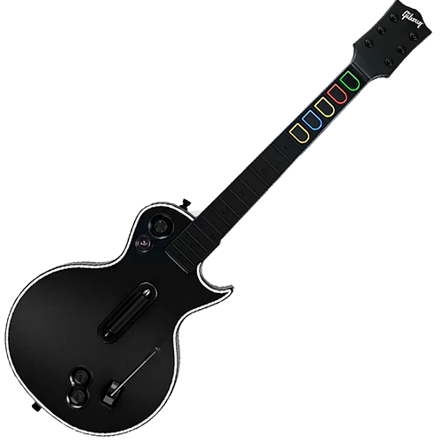
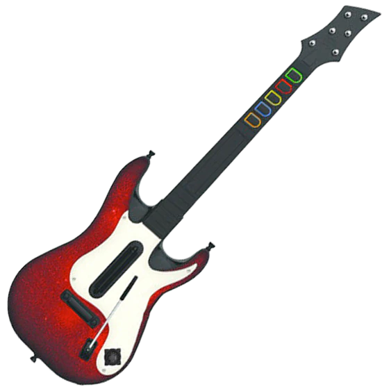
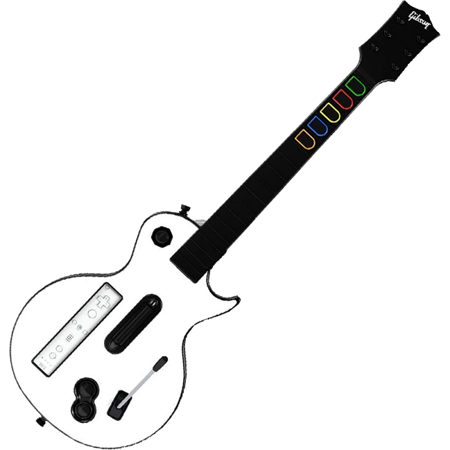
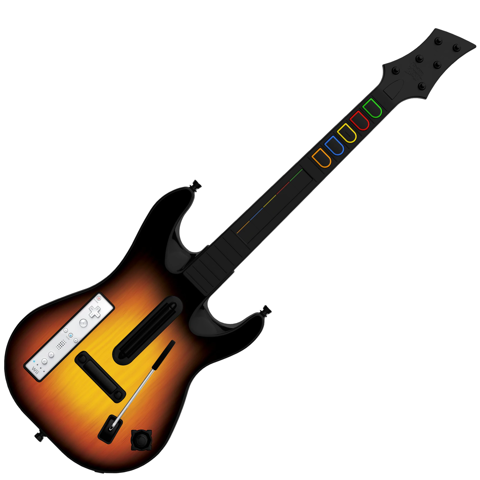
Only the Xbox 360 and PS3 variants of the Les Paul, World Tour, and GH5 models have D-Pads. We do not provide soldering instruction for the stock d-pads of those guitars. Replacements D-Pad Boards can be purchased here.
D-Pad Replacement Board Soldering Guide
Tools used:
Soldering Gear
Flush Cutters
Wire Strippers
26AWG Wire
Components:
Replacement D-Pad Board
Zeroboard
We do not provide support for the following D-Pad boards:
Observe the solder pads on the USB-C daughterboard, they match the pads on the Zeroboard.
3
Prepare four wires with stripped ends, in different colors.
4
You will need to solder each cable one by one carefully.Tin your soldering iron and clean it with brass wool.
5
Apply a small amount of flux to the pad you’re soldering to, making sure to be careful as to not touch anything but the wire, pad, and solder during the soldering process.
6
Repeat this for all four wires.
7
IMPORTANT
Do a thorough check of each solder joint to make sure nothing is bridging.
8
Test the new USB-C port by plugging the USB cable into the daughterboard, then into your computer. It should work in the same way as the USB-C port on the strumboard.
Your default preset. You don’t really ever need to leave this preset unless you’re having issues or are playing on PS2/Wii.
RB Guitar
Necessary for PS2 and Wii gameplay. It also can be used for RB Guitar passthru on RPCS3, but that’s a more advanced thing.
GH Guitar (Debug)
If you find that your guitar is automatically going into keyboard mode (green/start) or Riffmaster Emulation mode (orange/select), use this preset to see which input is having issue in the RCM Programming Tool input tester.
To play Rock Band 4 on your Xbox with a MiniHost Adapter, you will have to authenticate the MiniHost with a licensed Xbox One or Xbox Series controller.
1
Turn on the Xbox One/Series, then using your Xbox controller, load into Rock Band 4.
2
Disconnect the Xbox controller from your Xbox One/Series. (Pop out batteries)
3
Connect the licensed Xbox controller into the female USB-A port on the V3 Adapter.
Xbox One – models 1537, 1697, and 1698
Xbox One S – models 1708 and 1797
Xbox Series S/X – model 1914
4
Plug the adapter into the console with the gamepad plugged in.
5
Wait a moment, then press start on the gamepad to verify the connection is made. On the “Join” screen, a guitar player should appear.
6
Unplug the licensed Xbox controller from your device.
7
Plug in your guitar, if applicable.
8
Play the game!
If your controller is connected under the profile you want to use for the guitar, you’ll need to “drop out” the controller before assigning that profile to the guitar.(image)
PC, Playstation 4/5, Xbox One/Series - Keyboard Mode
NOTE: EPIC HAS CHANGED A SETTING IN FORTNITE THAT HIDES PRO MODES NORMALLY. YOU WILL WANT TO ADJUST THIS TO ALWAYS HAVE PRO MODES SHOWING. TO FIX THIS:GO TO Settings > GAME > scroll to bottom > change “Always Display Pro Parts” to ON.
This will put your guitar into keyboard mode, where your inputs will be assigned to the default Fortnite Festival Pro Lead Keyboard settings:
1-5 for frets
Right Ctrl & Right Shift for strum
Forward Slash (/) for whammy
Page Down for overdrive
You will know it’s working if your instrument changes when you press the frets in the Festival Main Stage Lobby.Note that you will have to control your menus/character movement with keyboard & mouse/other controller, but once you load into the game from the Festival Main Stage, the guitar will function as intended! Have fun!
Nintendo Switch
NOTE: You will have to switch between two modes while navigating and playing, so be ready to do that often.MODE SWITCH BUTTON COMBO:
(press and hold yellow first, then tap start once)
1
You want your MiniHost Adapter to be on the Default (GH Guitar) preset. If you have changed yours to be something different, please download the latest RCM Programming Tool and factory reset it back to Default. You will have to calibrate your whammy (and tilt if needed).
2
Turn on your Nintendo Switch and plug your adapter/guitar in! It should be able to navigate the NS menu immediately. If not, unplug and plug in the adapter/guitar again.
3
Once you have confirmed that your adapter/guitar is working on the Switch, open Fortnite Festival.
4
Once the game is open, you should be able to navigate the game with the guitar, at least somewhat.
5
Open your game settings, then switch to the GAME tab. Scroll to the bottom and switch the “ALWAYS DISPLAY PRO PARTS” to ON.
6
Load into Fortnite Festival Main Stage, then select your songs. Once you ready up, HOLD YELLOW then tap START. Your guitar should then function to for play!
7
After your song is over, do the YELLOW+START combo again to be able to navigate.
My DIY Zeroboard is not appearing in the RCM Programming Tool
There are multiple potential reasons for this occurring.
Faulty USB cable or PC USB port. Using the same cable, try a different port, then switch the cable.
Lastly, you may just need to hard reset the device. Hold the reset button (small gold button on the Zeroboard) while plugging the Zeroboard in will put it into recovery mode, which will make a drive named “RPI-RP2” appear on your computer.
Windows Defender is stopping the RCM Programming Tool from opening
The RCM Programming Tool will sometimes get blocked by Windows Defender or other antivirus software. This is a false positive. The pop-up tends to occur due to the tool being freshly made (we have to recompile the programmer every time we update revisions).You can just click Run Anyway.
macOS won't let me open the RCM Programming Tool
e
The RCM Programming Tool is not seeing my device on Linux
If the RCM Programming Tool is not seeing your device, it is likely due to a permissions issue in Linux.You will need the following file:
Navigate to /etc/udev/rules.d/, then drop 68-RCM.rules into the folder.Once you’ve done that, open the RCM Programming Tool. Your device should appear now! If not, try unplugging and plugging back in.
My DIY Kit Guitar is not working in BetterGH3 on SteamOS/Bazzite/Linux